SK-YJ000HWXCHT-KP 100015
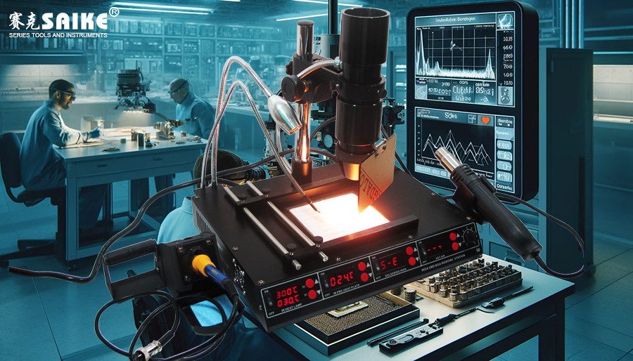
In the field of electronic manufacturing and maintenance, the infrared rework station, with its precise heating control and uniform heating effect, is particularly suitable for the disassembly and assembly of high-precision components such as BGA (Ball Grid Array) and QFP (Quad Flat Pack). These high-density packaged components have strict requirements for heating methods and temperature control, and the special application of the infrared rework station ensures their safety and integrity during the disassembly and assembly process. This article will explore in detail the application strategies and techniques of the infrared rework station in the disassembly and assembly of high-precision components such as BGA and QFP.
I. Technical Challenges of BGA and QFP
1.BGA (Ball Grid Array):
– Structure: The pins of the BGA package are arranged in a ball-shaped solder joint at the bottom of the component, usually connected to a multilayer circuit board.
– Challenge: The solder joints are hidden at the bottom of the package and cannot be directly observed during disassembly and assembly. It is necessary to uniformly heat the bottom solder joints and maintain stable temperatures.
2.QFP (Quad Flat Pack):
– Structure: The pins of the QFP package are arranged around the component, suitable for high-density electronic components.
– Challenge: The solder joint spacing is extremely small, and poor temperature control can easily lead to cold solder joints or damaged pins.
II. Special Application Strategies of Infrared Rework Station
1.Uniform Heating and Zoning Control:
– Principle: The infrared rework station utilizes precise control of the infrared emitter to ensure uniform heating of the BGA and QFP solder joint areas.
– Application Strategy: Adopt multi-zone temperature control technology to independently heat the target areas of BGA and QFP to prevent excessive heating of adjacent solder joints.
2.Temperature Curve and Programming:
– Principle: Achieve gradual heating and stable cooling through preset temperature curves or programming to ensure stable temperatures throughout the heating process for solder joints and components.
– Application Strategy: Adjust the temperature curve during the preheating, heating, and cooling phases for BGA and QFP components, ensuring a constant temperature near the solder melting point for a sufficient duration to achieve soldering or desoldering.
3.Local Heat Insulation and Shielding:
– Principle: Use heat-insulating materials or reflective covers to isolate and protect non-target areas, preventing heat damage to other sensitive components.
– Application Strategy: Provide heat insulation protection for adjacent vulnerable components and solder joints during the disassembly and assembly of high-precision components, ensuring that only the target area is heated.
4.Real-time Temperature Monitoring and Feedback:
– Principle: Infrared or thermocouple sensors monitor the temperature of BGA or QFP solder joints in real-time, providing data feedback to the control system to ensure temperatures remain within a safe range.
– Application Strategy: Adjust heating power and time based on real-time temperature data to ensure stable solder joint temperatures, preventing overheating or insufficient heating.
III. Practical Operation Techniques
1.Precise Positioning:
– Positioning Method: Utilize the optical system of the infrared emitter or visual aids to precisely locate the target areas of BGA and QFP, ensuring heating is focused on the target solder joints.
2.Adjusting Temperature and Time:
– Temperature Adjustment: Set appropriate temperatures based on the solder melting point and component heat resistance, ensuring a low and constant temperature during the preheating phase to avoid sudden increases.
– Time Adjustment: The preheating time should be sufficient to ensure uniform heating of the solder joints and reach the solder melting point.
3.Solder Joint Cleaning and Testing:
– After disassembling the BGA and QFP components, clean the solder joint surface to ensure no residual solder or oxides.
– Use soldering test equipment to confirm the integrity of the solder joints, avoiding cold solder joints or short circuits.
IV. Summary
The infrared rework station provides safe and effective heating support during the disassembly and assembly of high-precision components such as BGA and QFP through precise temperature control and real-time monitoring technology. Strategies such as multi-zone heating, preset temperature curves, and local heat insulation ensure the integrity of solder joints and the safety of components. Adjusting temperature and time, precisely positioning solder joints, and monitoring temperature feedback during practical operations can improve the success rate of high-precision component disassembly and assembly, ensuring a high quality level in electronic manufacturing and maintenance.


