SK-YJ000HWXCHT-KP 100027
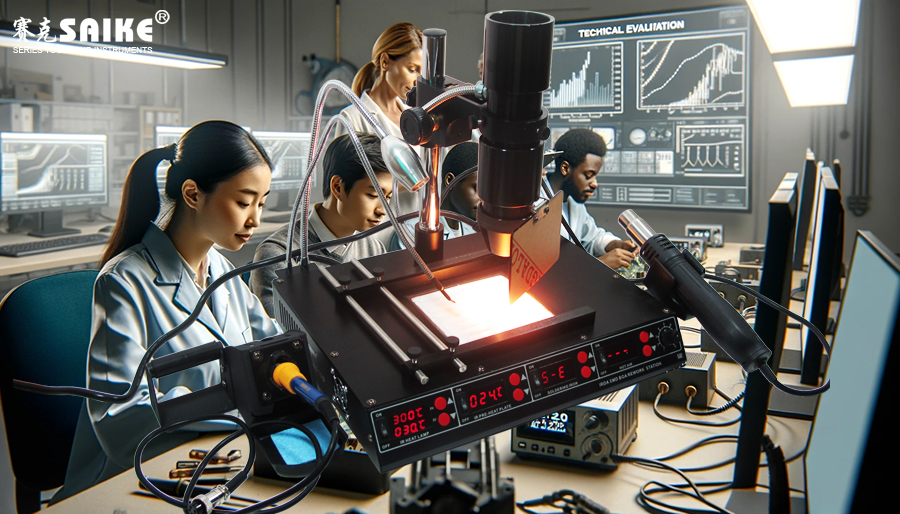
The infrared desoldering station is an advanced electronic repair tool that requires operators to possess adequate technical knowledge and practical skills to perform efficient soldering and desoldering operations on high-density, complex circuit boards. Through the demonstration and technical evaluation of trainees operating the infrared desoldering station, their operational level can be deeply understood, and room for improvement can be identified. This article will detail the demonstration methods, evaluation points, and common issues encountered by trainees operating the infrared desoldering station, aiming to help technicians optimize their learning and practical effects.
I. Preparation for Operation Demonstration
1.Equipment and Material Preparation:
– Ensure that all components of the infrared desoldering station are functioning properly, including the infrared emitter, temperature control system, and optical positioning system.
– Prepare multilayer circuit boards, high-density components, solder, insulation materials, protective equipment, etc., to simulate a real operating environment.
2.Preset Temperature Curve:
– Set a reasonable temperature curve for different types of circuit boards and solders to ensure stable temperatures during the preheating, heating, and cooling phases.
– The preheating temperature should be controlled between 100°C and 150°C, and the soldering temperature should be slightly higher than the melting point of the solder.
3.Learning Objectives and Demonstration Steps:
– Clarify learning objectives for trainees, such as soldering or desoldering high-density solder joints, uniform preheating of multilayer boards, etc.
– Develop detailed operational demonstration steps to ensure accuracy at each stage of the operation.
II. Key Steps and Technical Points of the Demonstration
1.Optical Positioning and Zonal Heating:
– Positioning: Utilize the optical system of the infrared desoldering station to accurately locate the target solder joint, and adjust the angle and focal length of the infrared emitter to ensure precise heating of the target area.
– Zonal Heating: Utilize the multi-zone heating function to control the temperature of solder joints in different zones for multilayer boards and high-density components.
2.Temperature Control and Curve Adjustment:
– Temperature Control: Monitor the solder joint temperature in real-time to ensure stability during the preheating and heating phases, avoiding excessively high or low temperatures.
– Curve Adjustment: Adjust the temperature curve parameters based on the type of solder and the structure of the circuit board to ensure the solder joint temperature reaches the optimal range.
3.Insulation and Shielding:
– Use insulating materials or shields to protect adjacent sensitive components or non-target areas, ensuring that heating is concentrated on the target solder joint.
4.Solder Joint Cleaning and Quality Inspection:
– After desoldering, use appropriate tools to clean the solder residue from the solder joints, ensuring that the surface of the solder joints is free of solder slag or oxides.
– Use inspection tools such as microscopes to check the surface and connection quality of the solder joints, ensuring there are no issues such as cold solders or false solders.
III. Key Indicators for Technical Evaluation
1.Heating Precision:
– Check the consistency between the heating range of the infrared emitter and the target solder joint to ensure concentrated and uniform heating.
2.Temperature Curve Accuracy:
– Evaluate whether the solder joint temperature aligns with the set temperature curve, ensuring stable temperatures with no fluctuations during the preheating, heating, and cooling phases.
3.Operational Step Standardization:
– Examine whether trainees strictly follow the operational demonstration steps for optical positioning, temperature control, insulation, and solder joint cleaning.
4.Solder Joint Quality:
– Inspect the surface and connection of the solder joints, ensuring there are no issues such as cold solders, false solders, or solder residue.
5.Safety Awareness and Efficiency:
– Evaluate whether trainees wear protective equipment, correctly use insulating materials, and complete operations within the specified time during the process.
IV. Common Issues and Solutions
1.Excessively High or Low Temperatures:
– Cause: Incorrect temperature curve settings, malfunctioning temperature sensors, or improper adjustment of heating power.
– Solution: Calibrate the temperature sensor, readjust the preheating and heating temperature curves, and ensure stable solder joint temperatures.
2.Deviation of the Heating Area:
– Cause: Inaccurate positioning of the infrared emitter or unstable fixation of the circuit board.
– Solution: Readjust the optical system to ensure accurate positioning of the infrared emitter on the target solder joint and stabilize the circuit board.
3.Cold Solders or False Solders:
– Cause: Insufficient melting of the solder or rapid heating of the solder joint.
– Solution: Reasonably adjust the temperature curve based on the solder type to ensure complete melting of the solder during soldering or desoldering.
V. Summary
Through the demonstration and technical evaluation of operating the infrared desoldering station, trainees can proficiently master key skills such as optical positioning, temperature control, and solder joint quality inspection through practical exercises. The technical evaluation should focus on indicators such as heating precision, temperature curve accuracy, operational step standardization, and solder joint quality. This allows for the identification of trainees’ deficiencies and prompt correction of common issues, ensuring that they can independently, safely, and efficiently use the infrared desoldering station in practical operations.


