SK-YJ000ZLWYDY-KP 100023
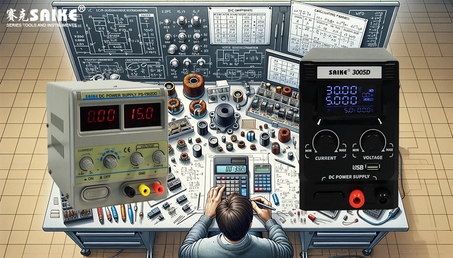
The correct selection and parameter calculation of key components are essential to ensure that the power supply meets performance and reliability requirements when designing a DC stabilized power supply. This article will introduce the selection and calculation methods of key components in DC stabilized power supplies, including inductors, capacitors, switching elements, and control ICs.
I. Selection of Switching Elements
1.Selection of MOSFET or IGBT
– Select based on the required maximum input voltage and output current. Ensure that the maximum voltage and current ratings of the switching element are higher than the required values for maximum operating conditions.
– Consider the on-resistance (Rds(on)) and switching speed, which directly affect conversion efficiency and switching losses.
2.Calculation of Thermal Losses
– Use the following formula to estimate thermal losses: Power Loss = Current² * On-Resistance (Rds(on))
– Note: This formula is used to estimate the heat generated on the switching element due to current flow. The smaller the on-resistance, the less heat loss.
– Determine the cooling requirements, such as adding heat sinks or fans if necessary.
II. Selection and Calculation of Inductors
1.Selection Basis
– Select the inductor based on the maximum output current and minimum ripple current. The saturation current of the inductor must be higher than the maximum output current of the power supply to avoid saturation.
2.Calculation of Inductance Value
– Use the following formula to calculate the inductance value: Inductance = (Output Voltage * (1 – Duty Cycle) * Switching Period) / Ripple Current
– Note: This formula helps determine the required inductance to ensure stable output voltage of the power supply while controlling the ripple current within a reasonable range.
– A larger inductance value results in smaller output ripple but higher volume and cost.
III. Selection and Calculation of Capacitors
1.Selection Basis
– The output capacitor must be able to support voltage fluctuations during the switching period of the load to reduce output ripple.
2.Calculation of Capacitance Value
– Use the following formula to calculate the output capacitance: Capacitance = (Output Current * Duty Cycle * Switching Period) / Allowable Voltage Ripple
– Note: This formula determines the required capacitance at the output to maintain a stable voltage output during the switching period of the switching element, reducing voltage fluctuations.
– Choose capacitors with low Equivalent Series Resistance (ESR) and Equivalent Series Inductance (ESL) to improve performance.
IV. Selection of Control ICs
1.Functional Requirements
– Select a control IC with the required functions, including PWM control, synchronous rectification, soft start, overvoltage protection, and short circuit protection.
– Consider the compatibility of the IC to ensure it can effectively cooperate with other components, such as matching the driving capability of the MOSFET.
V. Summary
In designing a DC stabilized power supply, the selection and calculation of each key component are based on the performance requirements of the entire system. Correct selection and precise calculation ensure efficient and stable operation of the power supply unit. Additionally, the testing and debugging phase is equally important, as it helps verify the reasonableness of component selection and the effectiveness of the overall design.


