SK-YJ000ZLWYDY-KP 100054
Project Purpose
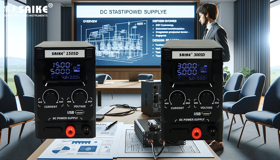
To design and implement a digital stabilized power supply that utilizes a microcontroller (such as Arduino or STM32) for precise voltage output control and dynamic monitoring. This power supply can be used in experiments, educational settings, or professional applications that require programmatic control and adjustment, allowing users to accurately adjust power supply parameters through a digital interface.
Basic Design Specifications
– Input Voltage: DC 12V
– Output Voltage: Adjustable, ranging from 0V to 12V
– Output Current: Maximum 2A
– Regulation Accuracy: ±0.1%
– Control Interface: USB or Bluetooth communication, supporting remote control
Technical Requirements
1.Microcontroller Selection and Programming
– Choose a microcontroller with sufficient analog input/output and communication interfaces, such as Arduino Uno or STM32.
– Write software to implement the user interface, voltage regulation, data logging, and communication functions.
2.Power Management Design
– Utilize a programmable switching regulator (e.g., TI’s TPS54331 or similar devices) for efficient power conversion.
– Design a digital control loop that uses the microcontroller’s PWM output and feedback input for precise control of the output voltage.
3.Protection and Safety
– Implement overcurrent, overvoltage, and short-circuit protection features.
– Incorporate a current detection circuit in the hardware, monitored by the microcontroller for real-time adjustment and protection.
4.User Interface and Remote Control
– Develop a simple user interface that allows users to adjust voltage and current directly on the device via an LCD display.
– Enable USB or Bluetooth-based remote control functionality, allowing users to remotely adjust and monitor the power supply via PC or smart devices.
Design and Development Process
1.Requirements Analysis and Planning
– Determine specific technical specifications and user needs.
– Plan the main development stages and timeline for the project.
2.Prototype Design and Testing
– Set up an initial circuit on a breadboard to test the interaction between the microcontroller and the power management chip.
– Write preliminary control code and test its performance under actual load conditions.
3.PCB Design and Manufacturing
– Design the PCB to transform the tested circuit into a more stable and professional onboard design.
– Manufacture and assemble the PCB, followed by system-level testing.
4.Software Development and Integration
– Develop the user interface and remote control functionality.
– Integrate all system components and conduct comprehensive functional testing and performance evaluation.
5.Product Validation and Optimization
– Invite potential users to test the product and make necessary optimizations based on feedback.
– Prepare technical documentation and user manuals to ensure effective product usage and maintenance.
Expected Outcomes
– A high-performance digital stabilized power supply that meets the needs of high precision and flexible control.
– Complete technical documents and user manuals, including design drawings, component lists, assembly instructions, and usage instructions for the user interface and remote control software.
– Market application: The power supply is suitable for R&D laboratories, educational institutions, and electronic product development, providing reliable and precise power solutions.
Through this project, the design team will gain valuable experience in digital power supply design and microcontroller programming, laying a foundation for the development of more complex power management systems.


