SK-YJ000ZLWYDY-KP 100034
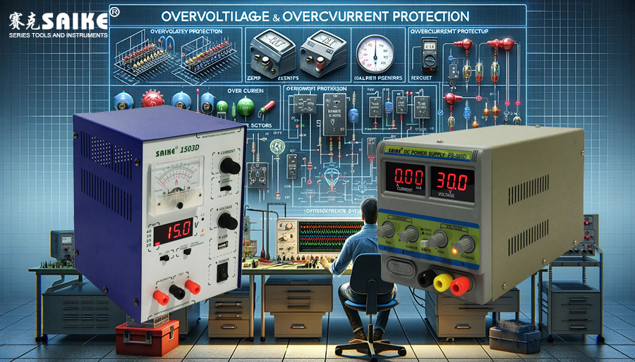
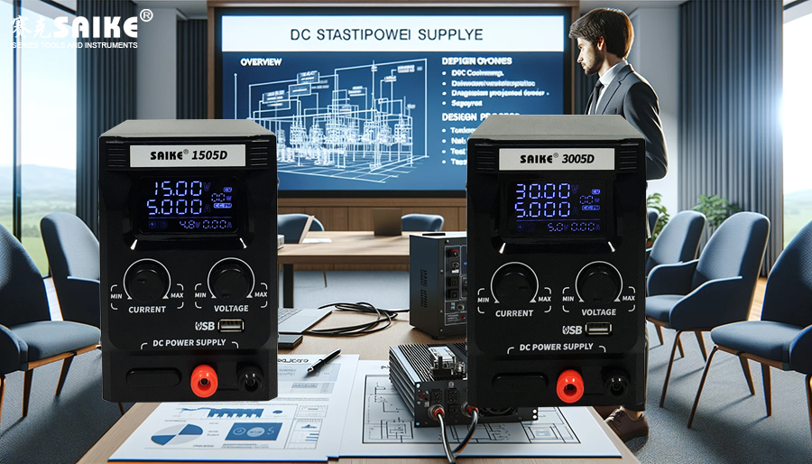
DC stabilized power supplies play a crucial role in the testing and operation of electronic equipment, ensuring that devices can operate safely and under predetermined voltage and current conditions. Therefore, overvoltage and overcurrent protection mechanisms are particularly critical in preventing damage to both the power supply and connected equipment. This article delves into the working principles, importance, and implementation methods of these two protection mechanisms in DC stabilized power supplies.
I. Overvoltage Protection
Overvoltage Protection (OVP) is a safety mechanism that prevents the power supply’s output voltage from exceeding a set value. This function is essential for protecting sensitive electronic equipment from damage caused by excessively high voltages.
1.Working Principle
– Overvoltage protection typically consists of a voltage detection circuit and control logic. The voltage detection circuit continuously monitors the output voltage. Once it detects that the voltage exceeds a predetermined safety threshold, it triggers the protection mechanism.
– After triggering, the power supply may respond by disconnecting the output or reducing the output voltage, thereby protecting the connected equipment.
2.Implementation Methods
– Using Zener diodes or TVS diodes to provide a quick response to suppress high voltages.
– Program-controlled electronic switches (such as transistors) are used to disconnect the power supply output until the fault condition is cleared.
II. Overcurrent Protection
The Overcurrent Protection (OCP) mechanism is designed to prevent the power supply’s output current from exceeding its maximum carrying capacity. This is crucial for preventing overheating and damage to both the power supply and the connected equipment.
1.Working Principle
– Overcurrent protection monitors the output current through a current detection circuit. When the current exceeds the safe range, the protection mechanism is activated.
– Protective actions typically include current limiting (reducing the output current to a safe level) or circuit breaking (completely cutting off the output current).
2.Implementation Methods
– A current sensor (such as a Hall-effect sensor) is connected in series in the power supply output loop to monitor the current in real-time.
– An electronic circuit breaker or resettable fuse is used to quickly disconnect the circuit when overcurrent is detected.
III. Design and Implementation Considerations
1.Accuracy and Response Time:
– The accuracy and response time of the protection mechanism are critical to its effectiveness. The design should ensure that these two parameters meet the protection needs of the power supply and the load.
2.Automatic Recovery and Manual Reset:
– After overvoltage or overcurrent protection is triggered, the power supply should have an automatic recovery function, allowing the equipment to automatically resume normal operation after removing the fault. Alternatively, it may require manual operation to reset the protection status, enhancing system security.
3.Synergy with Other Protection Functions:
– Overvoltage and overcurrent protection often work in synergy with other safety features, such as over-temperature protection and short-circuit protection, to fully protect the power supply and connected equipment.
IV. Summary
Overvoltage and overcurrent protection play crucial roles in the design of DC stabilized power supplies. They not only protect the power supply itself from damage but also ensure that the connected load equipment operates in a safe and controlled electrical environment. By adopting advanced sensing and control technologies, the efficiency and reliability of these protection mechanisms can be greatly improved, providing users with higher safety guarantees. When designing, the interaction and integration of these systems should be fully considered to ensure the overall stability and safety of the power supply system.


