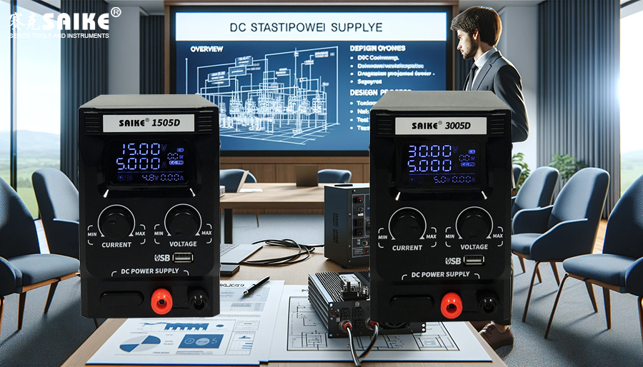
SK-YJ000ZLWYDY-KP 100024 Using Simulation Software for DC Stabilized Power Supply Design
DC stabilized power supplies play a crucial role in electronic devices, ensuring stable operation of equipment under constant voltage. When designing a stabilized power supply, using simulation software can effectively predict the performance of the power supply design and improve the accuracy and efficiency of the design. This article will explore how to use simulation software for DC stabilized power supply design, involving selecting appropriate software, establishing circuit models, conducting simulation analysis, and optimizing designs.
I. Choosing Simulation Software
1.Considerations for Software Type:
– Functional comprehensiveness: Whether the software supports various circuit components and analysis tools required for power supply design.
– User interface: Whether the software is easy to use and whether the interface is intuitive.
– Cost-effectiveness: The degree of matching between software cost and budget.
2.Commonly Used Simulation Software:
– LTspice: Developed by Linear Technology, it is optimized for power management and power circuit design, powerful and free.
– PSIM: Specifically designed for power electronics and motor control, supporting complex power circuits and system-level simulations.
– Multisim: Provided by National Instruments, user-friendly, suitable for education and industrial applications.
II. Establishing Circuit Models
1.Determining the Circuit Architecture:
– Linear regulator: Such as LM7805 for simple applications.
– Switching regulator: Suitable for high-efficiency, high-output current scenarios.
2.Selecting Circuit Components:
– Choosing voltage regulator ICs, inductors, capacitors, and related protective components.
– Selecting appropriate model parameters based on the operating frequency and power of the components.
3.Circuit Connection and Layout:
– Correctly placing components in the software and making electrical connections.
– Considering the circuit layout and grounding strategy to reduce noise and interference.
III. Conducting Simulation Analysis
1.Setting Simulation Parameters:
– Defining the range of input voltages and output load conditions.
– Setting the time scale and resolution of the simulation.
2.Running the Simulation:
– Observing voltage stability, efficiency, and temperature rise.
– Checking for risks of overvoltage, overcurrent, or thermal overload.
3.Analyzing Simulation Results:
– Using the simulation software’s graphical and data analysis tools to evaluate the results in detail.
– Determining whether adjustments to the design are needed, such as replacing components or modifying the circuit layout.
IV. Optimizing the Design
1.Adjusting Component Parameters:
– Adjusting the size of inductors, capacitors, or specifications of other key components based on simulation results.
– Considering the use of higher-performance components to improve the efficiency and response speed of the regulator.
2.Iterative Simulation:
– Re-simulating the modified design to verify improvement effects.
– If necessary, optimizing repeatedly until all design requirements are met.
V. Summary
Using simulation software for DC stabilized power supply design can significantly improve design efficiency and reliability. Choosing suitable simulation tools, accurate modeling, exhaustive analysis of simulation results, and optimization based on these results are key steps to successful design. Although initial learning and setup may require time and resource investment, in the long run, this approach can significantly reduce costs and time during the actual testing phase, improving product competitiveness and market performance.


